Building an Auto Water System for Your Plants
Introduction
I’m terrible at keeping plants alive so I figured I’d automate the process. The basic idea is to use the resistivity of the soil to determine how much water is needed and controle a pump and a solenoid valve with an arduino to provide water when the plant dries out enough. Let’s get started.
Resistivity of Soil
In order to determine when the plants need water. We first have to figure out how dry the soil is. I’m going to do this by building a basic soil sensor. This can be done by placing two nails close together. The damp soil between the nails will act as a a resistor and we can look at the way this resistivity changes in order to figure out how damp our soil is. I made a simple sensor out of some scrap wood and two nails placed 1 cm appart.
This is all fine and good but how can we figure out how much resistance the sensor has at any given moment? Well I’m going to give you the answer and then walk through it. We’ll use a simple circuit displayed in Figure 2 called a voltage divider. The voltage divider gives us the ability to look at the drop in voltage caused by a resistor which is enough to tell us it’s resistivity. The derivation is super simple all we need is Ohm’s law and the fact that in series resistance is additive. Let’s begin. We know that the total voltage from \(V_{cc}\) to ground is \(V_{cc}\). By Ohm’s law that means that we can calculate:
\[V_{cc} = IR\]We also know that because our soil sensor is in series with another resistor:
\[R = R_1 + R_2\]This gives us an expression for the total current traveling through the wire:
\[I = \frac{V_{cc}}{R_1 + R_2}\]The last step is to figure out what the voltage at \(A_0\) is let’s call this \(V_A\). Since the current traveling through \(R_1\) and \(R_2\) is identical we have that:
\[V_A = IR_1\]Plugging this back into our last equation for \(I\) we get our equation for the voltage drop accross our sensor! \begin{align} V_A &= \frac{V_{cc} R_1}{R_1 + R_2}\newline R_2 &= \frac{R_1(V_{cc} - V_A)}{V_A}\newline R_1 &= \frac{R_2V_A}{V_{cc} - V_A} \end{align}
For the actual system it really doesn’t matter whether you’re measuring the resistance between the leads or just the measured voltage at the divider point. For simplicity, I’m just going to use the voltage measurement to determine when to water or not. I then assessed the measured voltage of completely dry potting soil and found it to be unsurprisingly 0 V. I then repeated this measurement adding a 1/4 cup of water at a time until the soil was saturated to my liking. I let the system settle and recorded the voltage drop. I found it to be .25V. This is going to be my threshold to water. Whenever the soil becomes drier that .25V I’m going to have the system water the plants.
Wiring
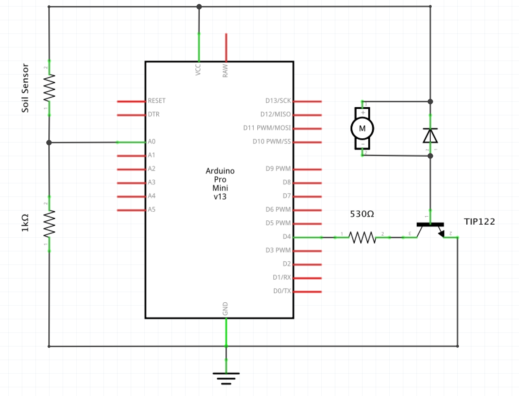
The wiring is pretty simple and can be seen in the figure below.
Controlling the Pump and Valve
I created a short Arduino program to controll the pump. All it does is read in the voltage across the soil sensor and when it drops too low provides 10 seconds of watering and then waits 20 seconds before repeating. It continues to water until the soil gets damp enough that the voltage rises above the threshold found in the above step.
#define NUM_SAMPLES_TO_AVERAGE 10  // number of analog samples to average
#define SOIL_VOLTAGE .15

int pump_pin = 4;

double sum = 0.0;                   // Summ of current sample set
int sample_counter = 0;             // Counts number of samples taken
double voltage = 0.0;               // voltage taken


void setup() {
  Serial.begin(9600);
  pinMode(pump_pin, OUTPUT);
}


void loop() {
  // Read in samples to be averaged
  while(sample_counter < NUM_SAMPLES_TO_AVERAGE) {
    sum += analogRead(A1);
    sample_counter ++;
    delay(20);
  }

  // Average Sum
  voltage = sum / (NUM_SAMPLES_TO_AVERAGE);

  //Convert to actual voltage (0 - 5 Vdc)
  voltage = (voltage / 1024) * 5.0;

  // Reset looping variables
  sum = 0;
  sample_counter = 0;

  // Write voltage to serial
  Serial.println(voltage);

  if (voltage < SOIL_VOLTAGE) {
    digitalWrite(pump_pin, HIGH);
    delay (5000);
    digitalWrite(pump_pin, LOW);
    delay(10000);
  }

}
All code and diagrams for this project can be found here